")
")
")
")
")
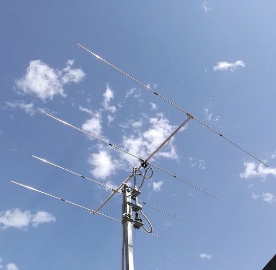
The Smartech 27Y4 belongs to the family of low native impedance Yagis. Its 4-meter boom, along with its typical excellent performance, place the antenna at the top of same-elements/same-boomlength category.
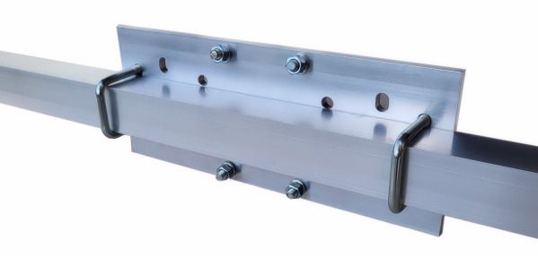
The antenna has a light but strong structure, particularly resistant to very severe mechanical loads. Thanks to the choice of the best materials and the specific sizing of each part, the structure has a strong elasticity and resistance even to the most energic wind loads.
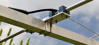
Nevertheless, the antenna is suitable for installations on stands and even rotors of small size.
The hairpin (beta match) matching system makes the 27Y4 DC Grounded, protected against electrostatic shocks to RTX devices.
The 27Y4 can be installed in both horizontal and vertical polarization. It's also suitable for stack installations in different configurations (contact the Smartech Technical Division for technical details and solutions).
| ELECTRICAL SPECIFICATIONS | |
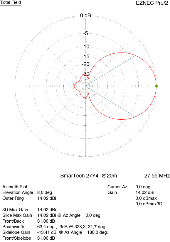
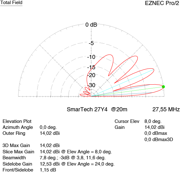
| Gain | 14.02dBi @20m (65.6ft) |
| Front/Back Ratio | 31dB @20m (65.6ft) |
| Impedance | 50 ohm |
| Power rating | 5.0 kW |
| Matching Method | Hairpin |
| 3 dB Horizontal Beamwidth | 66°@8m (26.2ft) |
| PHYSYCAL AND MECHANICAL SPECIFICATIONS | |
| Weight | 9.3kg (20.5lb) |
| Boom length | 4m (13.1ft) |
| Longest element | 5.5m (18.1ft) |
| Rotation radius | 3.4m (11.2ft) |
| Projected area [F=Flat - C=Cylindrical] | F = 0.63 m²(6.8 ft²) - C= 0.268m² (2.885 ft²) |
 |
 |
MATERIALS
The main structure of the antenna is made of aluminum alloy EN AW-6060/82 UNI9006 / 1 (Anticorodal 60/100), which gives greater durability against the most aggressive atmospheric agents (ice, water, UV rays, fine dust, acid rain), and a better resistance to the mechanical stresses of the wind.
SmarTech antennas are also supplied, depending on the models and specific mechanical requirements, with parts in Aisi 304 stainless steel (Austenitic Stainless Steel UNI / EN 10088) and parts in steel compliant with the resistance classes designated by the EN ISO 898-1 standard: 2013.
The insulators blocks are in POLYPROPYLENE PPC 5660, a material resistant to considerable thermal excursions (from -20 ° C to + 130 ° C), with high breaking load (tensile strength 25Mpa), good resistance to abrasion and volume resistivity> 1018
The antenna is designed to achieve maximum electrical efficiency and the best mechanical strength and durability, thanks to the quality of the materials used.
It is also suitable for installation in particularly aggressive environments, such as high altitude mountainous areas or coastal areas with a highly corrosive atmosphere.
SmarTech antennas are made with materials and technological solutions that minimize parasitic resistances (which produce unwanted RF dissipations) along the entire radio frequency signal path.

What Our Customers Say
Filippo 1AT783 - Italy
__________________________
| ELECTRICAL SPECIFICATIONS | |
| Gain | 14.02dBi @20m (65.6ft) |
| Front/Back Ratio | 31dB @20m (65.6ft) |
| Impedance | 50 ohm |
| Power rating | 5.0 kW |
| Matching Method | Hairpin |
| 3 dB Horizontal Beamwidth | 66°@8m (26.2ft) |
| Stacked Distances | 5÷8m (16.4÷26.2ft) |
| 2 Stacked Gain | [8m/26.2ft Stacking Distance]
16.5dBi @11m (36 ft) [5m/16.4ft Stacking Distance] 15.9dBi @9m (29.5 ft) |
| 2 Stacked F/B | [8m/26.2ft Stacking Distance]
18.7dB @11m (36 ft)) [5m/16.4ft Stacking Distance] 21.2dB @9m (29.5 ft) |
| PHYSYCAL AND MECHANICAL SPECIFICATIONS | |
| Weight | 9.3kg (20.5lb) |
| Boom length | 4m (13.1ft) |
| Longest element | 5.5m (18.1ft) |
| Rotation radius | 3.4m (11.2ft) |
| Projected area [F=Flat - C=Cylindrical] | F = 0.63 m²(6.8 ft²) - C= 0.268m² (2.885 ft²) |